Quick Guide
Workflow
- Design the schematic on the left. Add components from the library and draw wires between pins to define nets.
- Place components on the stripboard on the right. Drag them from the unplaced tray onto the board.
- Resolve conflicts. Place cuts to isolate strips and add wires to connect separated nets.
- Done. When all nets are complete and there are no conflicts, you are ready to solder.
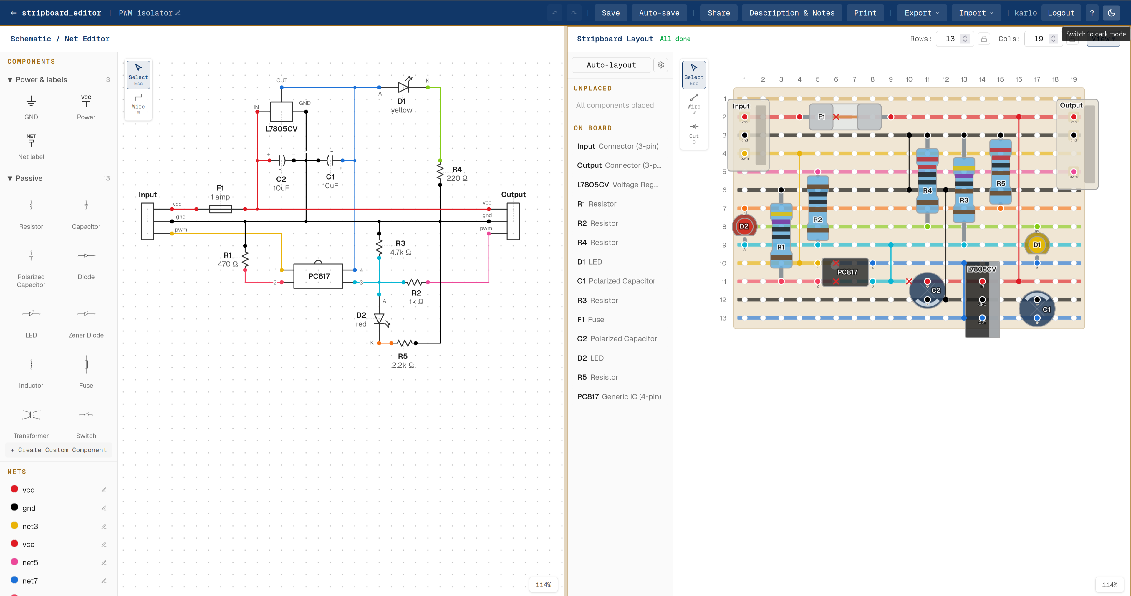
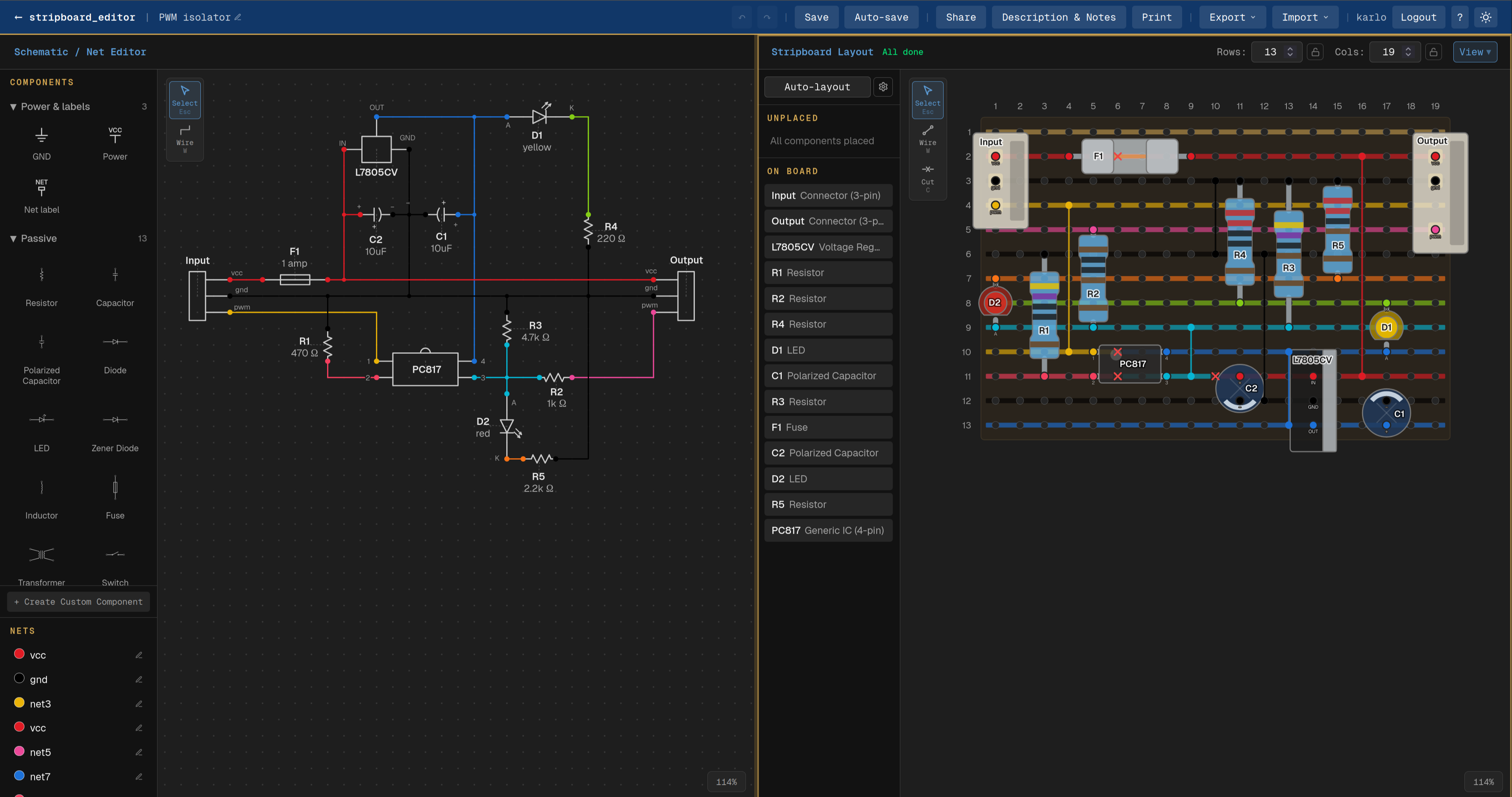
A finished project: schematic on the left, stripboard layout on the right.
Schematic Editor (left)
Adding parts and wires
- Drag components from the library onto the canvas. + Create Custom Component at the bottom of the library makes your own; it is saved with the project.
- Click a pin end to start a wire, then click pins, wires or grid points to route it. The wire tool (W) also starts wires on empty grid.
- Click a component label or a pin label to rename it. Drag labels out of the way.
What counts as connected
- Whatever touches is connected: a wire end on a wire, a pin on a wire, two pins on one point. Wires that only cross stay separate.
- A dot marks a junction, a small hollow square a loose wire end.
- Connected pins form a net. Rename or recolour nets in the sidebar.
Flags and net labels
- Ground and power flags (G / P) and net labels (L) join everything of the same name into one net, so GND and VCC need no wires across the sheet. Double-click a flag to rename it.
Selecting and editing
- Click selects, Ctrl + click toggles, Shift + click adds. Wires are selected and moved like parts.
- A box dragged left to right selects what it encloses, right to left everything it touches.
Parts that are not on the board
- Mount off board (floating menu) is for pots, switches and jacks on the enclosure. The board gets solder pads or a connector for their wires instead of the part.
- Exclude (E) keeps a part in the schematic but ignores it on the board and in its net checks, so you can draw a full circuit and build only part of it.
Older projects and the Classic wiring link
Schematics drawn before touching meant connected follow the rules they were drawn under, where only wire ends connect. Drawings that mean the same under both sets of rules were switched over for you. The rest show a Classic wiring link in the schematic header that previews every change the switch would make and applies it. The switch is optional, and undoable.
Protoboard Editor (right)
Placing parts
- Drag components from the Unplaced tray onto the board. Strips take the colour of the net on them; a red strip carries two nets and needs a cut.
- 2-pin parts like resistors and LEDs have flexible leads. Drag a single pin to reshape them.
- A part that puts two of its pins on one strip, like an IC, brings the cuts between them when you place it. They move with the part and leave with it.
- Hover an incomplete net in the sidebar to highlight its strips.
The tools: select, wire, cut
- The tools on the left edge of the board decide what a click does. Esc always returns to select.
- Wire (W): click a hole, then another. Wires already in a hole are ignored, so a chain can hop on from the same hole.
- Cut (C): click a hole to drill it out, or between two holes to cut the copper there. It works under parts too. Click a cut again to remove it.
- Select: move parts, and click a wire or a cut to drag or delete it. Drag a wire end to move just that end.
Rows and columns
- Right-click anywhere on the board to insert or delete the row or column there. Deleting unplaces parts that sit on the line; whatever only spans it shrinks.
Footprints and packages
- Select a placed part and use the floating menu: Package picks the real body (a 1/4 W or 1/2 W resistor, TO-92 or TO-220), Edit Footprint resizes the grid and moves pins of ICs and connectors to match your physical part.
Auto-layout
Click Auto-layout above the unplaced tray. The layouter places every part, picks the board size, and adds the cuts and link wires. If anything cannot be completed, a pop-up tells you what and why.
- Lock the board size. Click the padlock next to Rows or Cols to keep exactly that many. A locked board cannot grow, so a few slanted or crossing wires may remain.
- Lock parts. Select placed parts and press L to keep them where they are. Locked layouts come out a little larger.
- Settings (gear beside the button): new layouts every run, drilled cuts only, no stacked wires, standing parts, extra room between parts, effort, and processor threads. Effort sets how many layouts are tried and how long each one searches; the panel shows how long a run will take on your machine. Each option explains itself in the panel.
Curious how it decides all this? How auto-layout works →
Printing & Assembly
- Print in the project toolbar builds an assembly guide. Print at 100% and check the calibration ruler, so the holes match real stripboard.
- The component sheet shows the top side: lay it on the board and push the leads through. The cut sheet is mirrored for the copper side and marks every cut with an .
- The BOM lists quantities, values and reference labels; off-board parts get a wiring table.
- Options: colour or black and white, reference and pin labels, and a view or edit QR code back to the project.
Exporting
- Export → Raw project downloads the whole project as a JSON file. Bring it back from the Import menu.
- Export → Netlist writes a KiCad netlist with your parts, values, pin numbers and nets, so a prototype can become a PCB. Most parts map to stock KiCad footprints; the rest come as a small footprint library in the same zip. Add it once under Preferences → Manage Footprint Libraries with the nickname shown in the pop-up.
- A netlist holds connections, not drawings, and importing one is not supported yet.
Saving & Sharing
- No account is required. The first save gives you a unique link; bookmark it to come back to the project.
- An account collects all your projects in one dashboard and adds sharing: an edit link for full access and a view-only link.
- Anyone viewing a shared project can fork it into their own editable copy.
Keyboard Shortcuts
Both editors
WWire tool on and off
RRotate the selection
DeleteRemove the selection
EscapeCancel, then clear the selection, then put the tool away
Arrow keysMove the selection one step (Shift: five)
Ctrl + ZUndo
Ctrl + Y / Ctrl + Shift + ZRedo
Right-click dragPan the canvas
Scroll wheelZoom in / out
Schematic
G / PGround flag / power flag at the cursor
LNet label at the cursor
MMirror the selection
EExclude / include the selected parts on the stripboard
Enter / BackspaceWhile drawing a wire: finish it / take the last segment back
Alt + DeleteRemove whole wires, all segments included
Ctrl + click / Shift + clickToggle / add to the selection
Ctrl + ASelect everything
Ctrl + C / Ctrl + V / Ctrl + DCopy, paste at the cursor, duplicate
Stripboard
CCut tool on and off
LLock / unlock the selected parts for auto-layout
Right-clickInsert or delete the row / column under the pointer
© 2026 Sadman Rahamat Bishalsadmanbishal.com