Protoboard Editor is a layout editor for prototyping boards. You draw a schematic, place the parts on a virtual board, and the copper takes the colour of your nets. A live check shows shorts and open connections. A list shows what still needs to be connected. When the layout is done, you print a template at true size and build it.
It runs in the browser, with no account and no install: sadmanbishal.com/Protoboard-Editor. The code is on GitHub, under GPL-3.0.
Where it comes from
It is a fork of Stripboard Editor by Karl Funke, which is licensed under GPL-3.0. That editor does stripboard very well, with a schematic editor, an auto-layouter and true-size parts. The fork keeps all of that. It adds the other kinds of board, a set of board size presets and some more parts. The licence stays GPL-3.0, as the original requires.
Four kinds of board
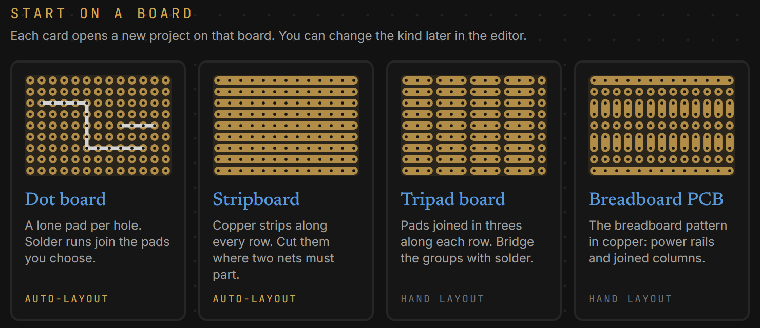
A stripboard has its copper strips in the board. On a dot board there is only a pad around each hole, and you join the pads with solder. Two more kinds sit in between.
| Board | Copper | Auto-layout |
|---|---|---|
| Stripboard | strips along the rows, separated with cuts | yes |
| Dot board | a pad per hole, joined with solder runs you lay | yes |
| Tripad board | pads joined in threes along each row, plus your runs | no |
| Breadboard PCB | power rails at the top and the bottom, blocks of five pads down each column, plus your runs | no |
On the pad boards there is a run tool. You click between two pads, or drag from pad to pad, and the editor lays a solder run along the way. The copper a board comes with stays as it is. Only the runs you add are yours.
From idea to board
- Draw. Build the schematic from the symbol library or from your own parts. The wires make the nets.
- Choose the board. Pick the kind of board on your bench and its size. The presets cover the common sizes, from 2 × 8 cm to 15 × 20 cm.
- Lay it out. Drag the parts onto the board, or let auto-layout do it. On stripboard it places the parts and lays the cuts. On a dot board it lays out strips first and then turns each strip into runs, only from its first to its last used hole.
- Print and solder. Print the 1:1 sheets, push the parts through the paper, and follow the cut sheet or the run sheet.
Parts are drawn as their real packages at true size, so the board on the screen looks like the board you build. The IC pinouts come from the KiCad symbol library, which is licensed CC-BY-SA 4.0.
The demo: a 555 LED flasher
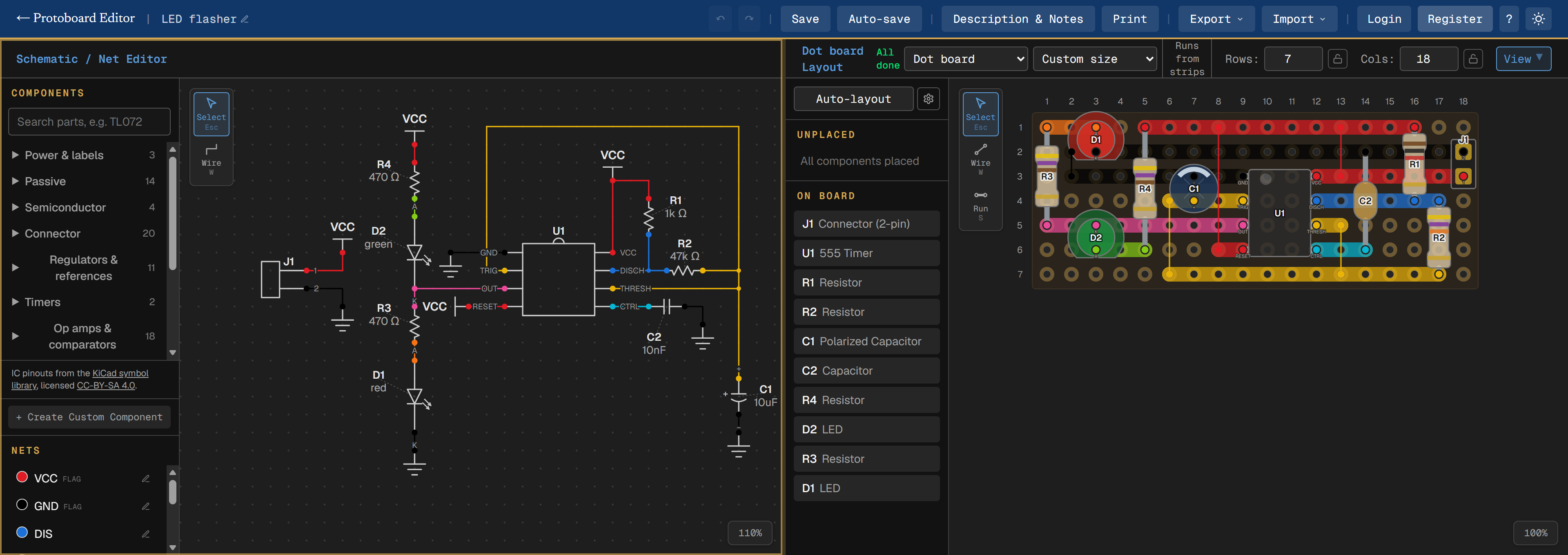
The circuit in the screenshots is a 555 timer that blinks a red and a green LED in turn. Auto-layout put it on a 7 × 18 dot board and laid 75 solder runs. The schematic is the same one you see on the left of the editor.
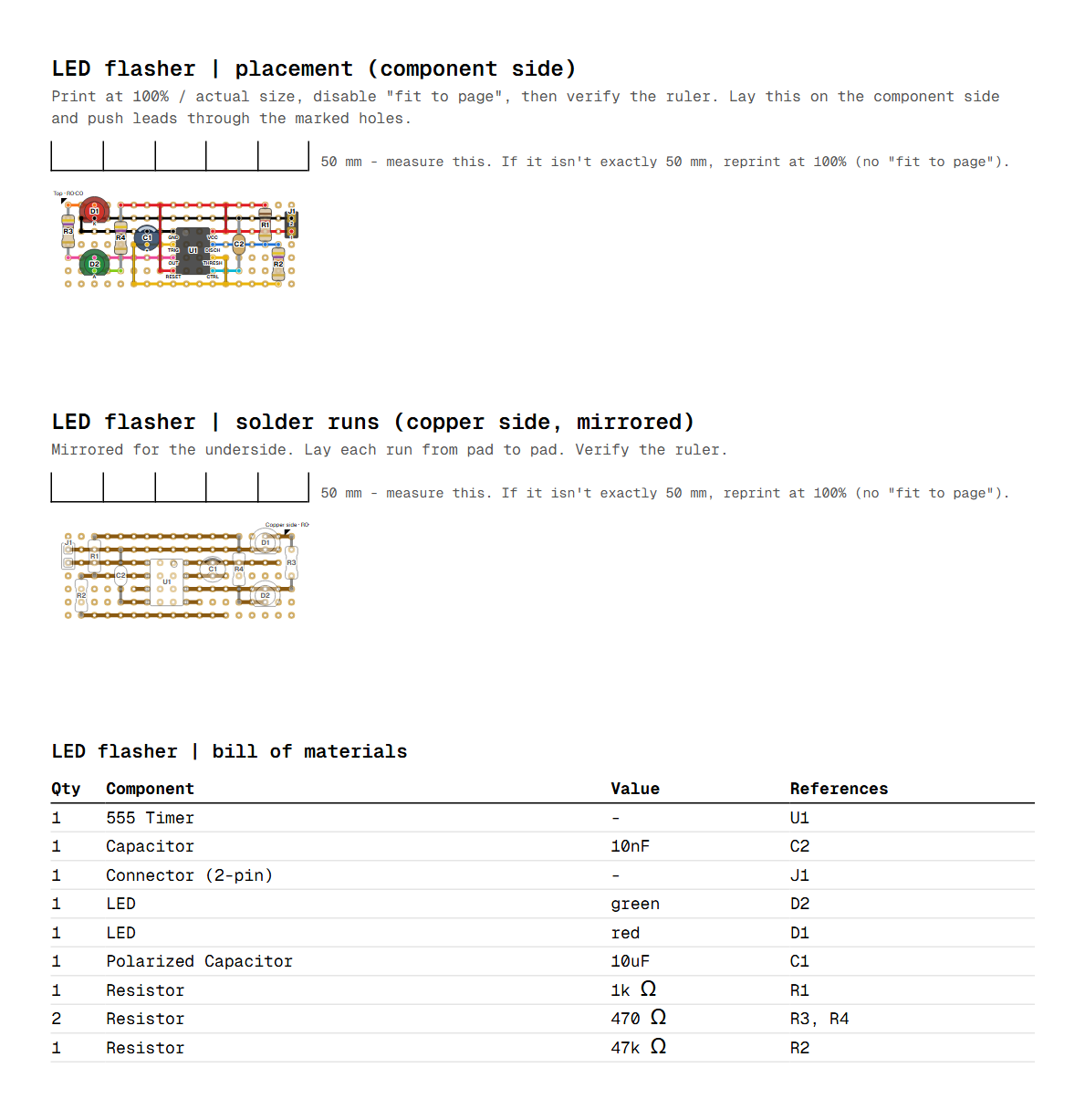
The print preview gives the sheets you build from: the placement sheet on top, then the run sheet, mirrored for the copper side, then the parts list.
When the prototype works, the editor exports a KiCad-compatible netlist, so you can draw the real PCB from the same circuit.
Two ways to run it
There are two builds of the same code.
- Browser-only. This is the version at the link above. Your projects stay in that browser, on that device. Clearing the browser data deletes them, so use Export to keep a backup file, and Import to open it again, also on another device. It has no accounts, no share links and no parts library.
- Self-hosted. This has everything: accounts, edit and view-only share links, a personal parts library, and projects stored on your server. It is a Next.js frontend and a Django backend with SQLite. You can run it on Windows, with Docker, or in Docker inside a Proxmox LXC container.
The browser-only build is a static export that GitHub Actions builds and publishes from the main branch.
Limits
- Only the 7 × 9 cm hole count (26 × 31) is counted on a real board. Count your own board and correct the rows and columns if they differ.
- Tripad and breadboard PCB boards have hand layout only. Auto-layout works on stripboard and dot board.
- The browser-only version cannot open project files from much older versions of the editor.
- The fork is young, and new board features land often.
If something breaks, or you have an idea, open an issue on GitHub.